Tiny85 Iambic Keyer Project
2022-July-10 - 2022-September-13
I wasn't planning on doing this particular project, but I can get kind of stubborn at times.
I've been trying to learn to send and receive Morse code so I can DX better, particularly when portable. I used to have a HF radio at my desk when I work from home, making it easy to practice. But, thanks to moving to a larger house, the ham shack and the home office are now in different rooms. Which has been great for work focus, but not so good for taking breaks and sending morse code when I'm trying to do a quick "two memory paths" memorization trick (I would tap out a quick message on the oscillator of what I was trying to memorize to engage more of my brain).
At first I wanted to get a Winkeyer, but they have been having supply issues. On Amazon I found that there were Micro USB development boards that had the Tiny85 controller plus a bootstrap that made it easy to program with the Arduino studio. So I've decided to create my own super cheap iambic keyer, I mean how hard could it really be?
After buying a few boards from Amazon I quickly realized that I was over my head. I had expected to be able to set the PWM controller in such a way I could generate a square wave at whatever pitch I wanted. Or in other words, let me tell you I've never done PWM in code without telling you that. It soon became obvious to me that I could come up with a square wave with the right timings, but I felt it would be hard to make the pitch variable because of the interaction between the duty cycle (has to stay at 50%) and the overall timing of the chips. So I searched the web for Tiny85 oscillator circuits and found a few notes about high quality PCM sound from a Tiny. This intrigued me. After reading a few articles here is my scheme I'll be pursuing:
- Use a Tiny86 usb development board.
- Minimum WPM less than 5 WPM.
- Maximum WPM over 30 WPM.
- Iambic keying (contact for dit, contact for dah, both pressed alternating dit / dah or dah / dit depending on which one closes first.
- PWM modulated PCM sound
- uses 5 of the six GPIO pins, reset will hopefully still be available for ease of reprogramming
- WPM controlled by a rheostat in voltage divider mode. This will have resistors on both sides to create a adjustment zone of about 1/3 of the possible voltages.
- The same GPIO pin will signal a raise in pitch or decrease in pitch by switches either pulling it low or high
Morse Code Speed
This project has already taken far too many hours over the last two weeks, and run me down a few rabbit holes. But I've learned a LOT. For starters, how Morse code timing is calculated.
PARIS ".--. .- .-. .. .../". Down in the references section of this article I link to an excellent article about Morse code timing. But let me sum it up here if I can in my own words. When they standardized the WPM measurements they decided that x WPM meant the ability to send the five letter word PARIS x number of times in a minute. So if I'm sending at 5 WPM PARIS will be sent five times. Morse code is a little tricky though because different letters are different lengths, so they have to choose the word that represents the perfect match of dits and dahs to make the timing work perfectly.
Morse code is a variable binary system. It alternates between signal and no signal, on or off. The information is carried by the timing of the on periods. The basic unit of timing is the period of the dit, and it's one unit of time. There is a longer unit called a dah, which is three time units long. Of course to hear that you have a dit or a dah you also need silence between each dit or dah there are a few different timings. When sending a character we wait one dit between each dit or dah. Between characters we wait the length of a dah, or three timing units. Finally between words you wait seven timing units.
- dit = 1 timing unit
- dah = 3 timing units
- Space between dits and dahs when sending character = 1 timing unit
- Space between characters = 3 timing units
- Space between words = 7 timing units
Coming back to PARIS, we have ".--. .- .-. .. .../", which if you compare the output with the list above equals 50 timing units. So we can multiply the number of words per minute we want to send at by fifty to get the number of timing units per minute. I believe that timing units per second is a little more useful, so divide sixty by the number of timing units to get timing units per second. In all but the slowest cases (less than 2 WPM), this will be a fraction of a second result.
For example five WPM = 5 * 50 = 250 timing units in a minute. So the length of a timing unit equals sixty divided by the number of timing units. I'll break this timing out from 1 WPM to 40 WPM in the table below.
| WPM timing units in seconds | |||||||
|---|---|---|---|---|---|---|---|
| WPM | Seconds | WPM | Seconds | WPM | Seconds | WPM | Seconds |
| 1 | 1.2000000000 | 11 | 0.1090909091 | 21 | 0.0571428571 | 31 | 0.0387096774 |
| 2 | 0.6000000000 | 12 | 0.1000000000 | 22 | 0.0545454545 | 32 | 0.0375000000 |
| 3 | 0.4000000000 | 13 | 0.0923076923 | 23 | 0.0521739130 | 33 | 0.0363636364 |
| 4 | 0.3000000000 | 14 | 0.0857142857 | 24 | 0.0500000000 | 34 | 0.0352941176 |
| 5 | 0.2400000000 | 15 | 0.0800000000 | 25 | 0.0480000000 | 35 | 0.0342857143 |
| 6 | 0.2000000000 | 16 | 0.0750000000 | 26 | 0.0461538462 | 36 | 0.0333333333 |
| 7 | 0.1714285714 | 17 | 0.0705882353 | 27 | 0.0444444444 | 37 | 0.0324324324 |
| 8 | 0.1500000000 | 18 | 0.0666666667 | 28 | 0.0428571429 | 38 | 0.0314789474 |
| 9 | 0.1333333333 | 19 | 0.0631578947 | 29 | 0.0413793103 | 39 | 0.0307692308 |
| 10 | 0.1200000000 | 20 | 0.0600000000 | 30 | 0.0400000000 | 40 | 0.0300000000 |
Addition: I just learned that there are other timing words that have been used instead of PARIS. CODEX was cited a common for the military because it worked better for code words made of random 5 character groupings, as well as some number standards for just sending numbers (12345 and 67890), each of these packs a different number of dots into a word, with PARIS having 50, CODEX 60, and I haven't done the math on the number standards. https://www.qsl.net/yo3fca/hstc.htm does a great job summarizing this. For my project I will stick with the PARIS convention.
Musical Tones
Morse code using the radio has never standardized on the pitch to use. This is largely because when tuning with a radio the pitch is determined not by the sender, but by the radio's reciever settings. These settings are easy to adjust and therefore not standard. But looking online it looks like the FCC has generally tested with a frequency between 700 Hz and 800 Hz. This makes sense from a general aquity of hearing perspective. I will note as I looked at high speed Morse code that the higher the pitch, the more cycles were present for a dit, which should make it easier to distinguish, but there is a tradeoff as hearing sensitivity seems to get damaged more easily at high frequencies. I know that my own tinitis makes higher pitches harder to hear than when I was a child.
For this sender I'd like to cover the pitches from around A above middle C (A4) up to about 1 kHz or C6. I was surprised as I researched tones to see that there have been several different tuning types used, and that while I'd always heard of A440, There was another tunning of ~A430 which made C4 256 Hz. As a computer guy that was intreiging, so I'm going to go for it. I calculated the scale as previous note * 2^(1/12). This isn't perfectly tempered and I know this will make some fifths and the like kind of strange, but it's an easy calculation this way and I believe close enough for the accuracy of a Tiny85 based oscillator that isn't playing Morse code along with an orchestra.
| C 256 | 0 | 1 | 2 | 3 | 4 | 5 | 6 | 7 | 8 | 9 | 10 |
|---|---|---|---|---|---|---|---|---|---|---|---|
| C | 16 | 32 | 64 | 128 | 256 | 512 | 1024 | 2048 | 4096 | 8192 | 16385 |
| c♯ / D♭ | 17 | 34 | 68 | 136 | 271 | 542 | 1085 | 2170 | 4340 | 8679 | 17358 |
| D | 18 | 36 | 68 | 136 | 271 | 542 | 1085 | 2299 | 4598 | 9195 | 18390 |
| D♯ / E♭ | 19 | 38 | 76 | 152 | 304 | 609 | 1218 | 2435 | 4871 | 9742 | 19484 |
| E | 20 | 40 | 81 | 161 | 323 | 645 | 1290 | 2580 | 5161 | 10321 | 20643 |
| F | 21 | 43 | 85 | 171 | 342 | 683 | 1367 | 2734 | 5468 | 10935 | 21870 |
| F♯ / G♭ | 23 | 45 | 91 | 181 | 362 | 724 | 1448 | 2896 | 5793 | 11585 | 23170 |
| G | 24 | 48 | 96 | 192 | 384 | 767 | 1534 | 3069 | 6137 | 12274 | 24548 |
| G♯ / A♭ | 25 | 51 | 102 | 203 | 406 | 813 | 1625 | 3251 | 6502 | 13004 | 26008 |
| A | 27 | 54 | 108 | 215 | 431 | 861 | 1722 | 3444 | 6889 | 13777 | 27554 |
| A♯ / B♭ | 29 | 57 | 114 | 228 | 456 | 912 | 1825 | 3649 | 7298 | 14596 | 29193 |
| B | 30 | 60 | 121 | 242 | 483 | 967 | 1933 | 3866 | 7732 | 15464 | 30929 |
Wave forms
PCM audio reproduces the original waveforms by measuring the voltage (which has a direct correllation to the volume) of the waveform as measured by the recording device. It was discovered that if you measure a sinewave at least twice its frequency you can reproduce it. I pondered working out the sampling rate and 8 bit magnitude levels for the frequencies I want to produce, and then it occured to me that I could use Audacity's sinewave generator filter to do the calculations for me.
There are two keys to how I'm doing this. First I set the project and track sample rate to match what I want to generate on the project. Then second, I save the generated trace as a unsigned eight bit wave file.
Then I'm using VIM and loading the wave file and converting it to a hex representation.
The command for this is
:%!xxd
which means take the whole content of the file and run it into the xxd utility, then replace the original text with the output of xxd. Here are a couple of screen shots of that process:
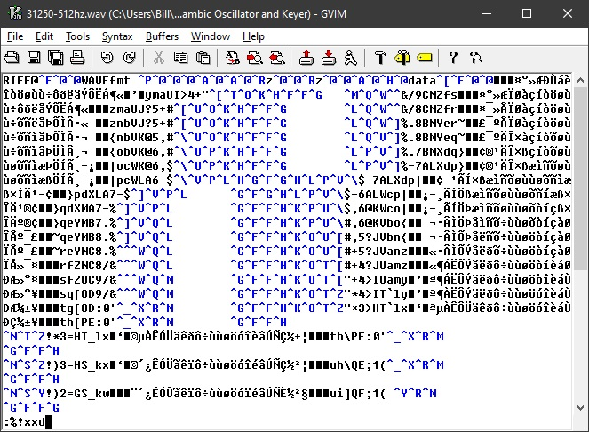
Raw wave file in VIM, note much of it is ctrl codes or otherwise unviewable.
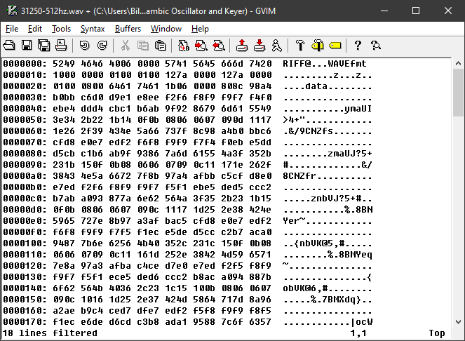
Now the file has a block of addresses from the start of the file, a block of byte values in hex, and a printable output block with unprintable bytes represented by a period.
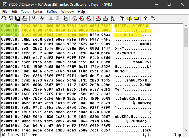
I've highlighted the header portion of the wave file, which describes the data to follow so a program a accurately decode it.
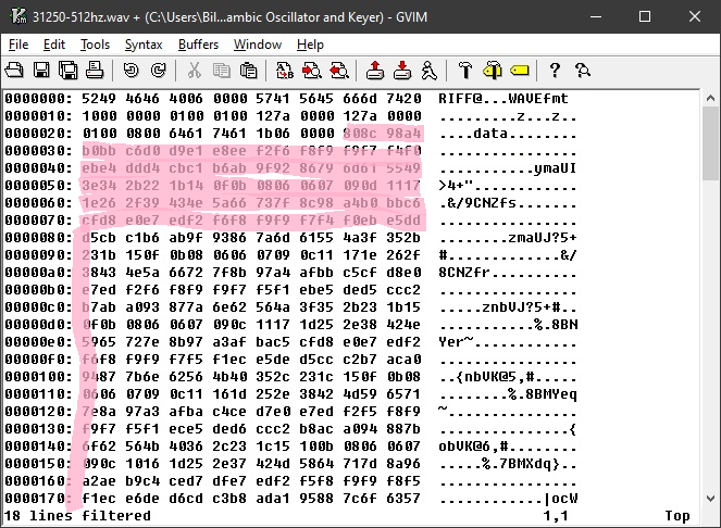
Finally, here is where the actual data begins, this is the section I'll cut out and convert.
Changes in plans
2023-March-19
Perfection is the enemy of done...
I'm still plugging away at this one, though life my life has been busy. It has been an excellent project for moving beyond theory. At this point in time I've switched from using a development board to a classic 8 pin din form factor chip. I bought a USB programmer module that makes programing the chip pretty easy. I did this so I could use two pins in variable mode that were otherwise tied down by the USB interfacing circuitry. This enables me to have a variable speed control as well as a variable pitch control.
At this point in time the iambic keying is pretty good at 18 WPM, and I'm getting pure sinewave output (if I don't turn up the volume too much). I need to fix / complete the following features:
- Variable pitch controls
- Variable speed control, all the way down being acting like a classic key controlled oscillator, then a bump to 5 WPM through thirty
- More amplification without distortion, at the moment turning up the volume even a little bit results in extreme distortion, I'm thinking my best bet at this point is to switch from a five volt amplifier circuit to a 12 volt circuit to get more headroom.
- Headphone jack with auto speaker disabling when connected
- Removing annoying click added to then end of each dot and dash, I believe this is caused by the waveform not going to zero at the end of the sound, and instead cutting off while the speaker is in the + or - side of the cycle.
I've got to go to bed now, but I'll update you all again when I have time.
Resources:
Morse Code Info:
- Morse Code World - Timing
- Real Marks speed system at IARU HST High Speed Telegraphy Championships (HSTC) — Morse code (CW) speed calculation
Musical Pitches
- Differences between 432 Hz vs 440 Hz
- Tuning - Frequencies for equal-tempered scale, A4=440 Hz
- Music Note to Frequency Chart
ATTiny85
Amateur Radio Technician Licensing Class
Feburary 3rd 2022
I've been teaching a class on the Technician Class Amateur Radio License exam.
I've been basing this on the question pool that expires June of 2022 figuring there is still time to pass that test. The next time I teach the class I'll adjust the material to cover the slight changes that the new question pool has made.
In the meantime, here are the power point slides for each class I've taught. I'll be adjusting this post each week until the class is over to add the next group of slides. I hope they help someone.
dBm, or deci Bells milliwatt, what does it mean?
9 January 2022
Often when dealing with electronics you will see the measurement dBm, and if you know about how dB works in general you can easily get the gist of what it is saying. But, unlike most of our dB readings, dBm is actually anchored to the value of a milliwatt. Why does this matter? It makes it easier to compare disparate systems, or engineer connections between them. For instance, I used dBm to decide how many dB of attenuation I had to add to my HF radio to be able to pipe it output into my SDR so I could see what my signal looked like.
So without any further ado, let me show my annotated dBm to wattage chart that includes both useful info, and some useless trivia.
| dBm | Watts | HF S Meter | VHF S Meter | Comments |
|---|---|---|---|---|
| -150 dBm | 1.00 aW | |||
| -149 dBm | 1.26 aW | |||
| -148 dBm | 1.58 aW | |||
| -147 dBm | 2.00 aW | |||
| -146 dBm | 2.51 aW | |||
| -145 dBm | 3.16 aW | |||
| -144 dBm | 3.98 aW | |||
| -143 dBm | 5.01 aW | |||
| -142 dBm | 6.31 aW | |||
| -141 dBm | 7.94 aW | S1 | ||
| -140 dBm | 10.00 aW | |||
| -139 dBm | 12.59 aW | |||
| -138 dBm | 15.85 aW | |||
| -137 dBm | 19.95 aW | |||
| -136 dBm | 25.12 aW | |||
| -135 dBm | 31.62 aW | S2 | ||
| -134 dBm | 39.81 aW | |||
| -133 dBm | 50.12 aW | |||
| -132 dBm | 63.10 aW | |||
| -131 dBm | 79.43 aW | |||
| -130 dBm | 100.00 aW | |||
| -129 dBm | 125.89 aW | S3 | ||
| -128 dBm | 158.49 aW | |||
| -127 dBm | 199.53 aW | |||
| -126 dBm | 251.19 aW | |||
| -125 dBm | 316.23 aW | |||
| -124 dBm | 398.11 aW | |||
| -123 dBm | 501.19 aW | S4 | ||
| -122 dBm | 630.96 aW | |||
| -121 dBm | 794.33 aW | S1 | ||
| -120 dBm | 1.00 fW | |||
| -119 dBm | 1.26 fW | |||
| -118 dBm | 1.58 fW | |||
| -117 dBm | 2.00 fW | S5 | ||
| -116 dBm | 2.51 fW | |||
| -115 dBm | 3.16 fW | S2 | ||
| -114 dBm | 3.98 fW | |||
| -113 dBm | 5.01 fW | |||
| -112 dBm | 6.31 fW | |||
| -111 dBm | 7.94 fW | S6 | ||
| -110 dBm | 10.00 fW | |||
| -109 dBm | 12.59 fW | S3 | ||
| -108 dBm | 15.85 fW | |||
| -107 dBm | 19.95 fW | |||
| -106 dBm | 25.12 fW | |||
| -105 dBm | 31.62 fW | s7 | ||
| -104 dBm | 39.81 fW | |||
| -103 dBm | 50.12 fW | S4 | ||
| -102 dBm | 63.10 fW | |||
| -101 dBm | 79.43 fW | |||
| -100 dBm | 100.00 fW | |||
| -99 dBm | 125.89 fW | S8 | ||
| -98 dBm | 158.49 fW | |||
| -97 dBm | 199.53 fW | S5 | ||
| -96 dBm | 251.19 fW | |||
| -95 dBm | 316.23 fW | |||
| -94 dBm | 398.11 fW | |||
| -93 dBm | 501.19 fW | S9 | ||
| -92 dBm | 630.96 fW | |||
| -91 dBm | 794.33 fW | S6 | ||
| -90 dBm | 1.00 pW | |||
| -89 dBm | 1.26 pW | |||
| -88 dBm | 1.58 pW | |||
| -87 dBm | 2.00 pW | |||
| -86 dBm | 2.51 pW | |||
| -85 dBm | 3.16 pW | s7 | ||
| -84 dBm | 3.98 pW | |||
| -83 dBm | 5.01 pW | S9 + 10 dB | ||
| -82 dBm | 6.31 pW | |||
| -81 dBm | 7.94 pW | |||
| -80 dBm | 10.00 pW | |||
| -79 dBm | 12.59 pW | S8 | ||
| -78 dBm | 15.85 pW | |||
| -77 dBm | 19.95 pW | |||
| -76 dBm | 25.12 pW | |||
| -75 dBm | 31.62 pW | |||
| -74 dBm | 39.81 pW | |||
| -73 dBm | 50.12 pW | S9 | S9 + 20 dB | |
| -72 dBm | 63.10 pW | |||
| -71 dBm | 79.43 pW | |||
| -70 dBm | 100.00 pW | |||
| -69 dBm | 125.89 pW | |||
| -68 dBm | 158.49 pW | |||
| -67 dBm | 199.53 pW | |||
| -66 dBm | 251.19 pW | |||
| -65 dBm | 316.23 pW | |||
| -64 dBm | 398.11 pW | |||
| -63 dBm | 501.19 pW | S9 + 10 dB | S9 + 30 dB | |
| -62 dBm | 630.96 pW | |||
| -61 dBm | 794.33 pW | |||
| -60 dBm | 1.00 nW | |||
| -59 dBm | 1.26 nW | |||
| -58 dBm | 1.58 nW | |||
| -57 dBm | 2.00 nW | |||
| -56 dBm | 2.51 nW | |||
| -55 dBm | 3.16 nW | |||
| -54 dBm | 3.98 nW | |||
| -53 dBm | 5.01 nW | S9 + 20 dB | S9 + 40 dB | |
| -52 dBm | 6.31 nW | |||
| -51 dBm | 7.94 nW | |||
| -50 dBm | 10.00 nW | |||
| -49 dBm | 12.59 nW | |||
| -48 dBm | 15.85 nW | |||
| -47 dBm | 19.95 nW | |||
| -46 dBm | 25.12 nW | |||
| -45 dBm | 31.62 nW | |||
| -44 dBm | 39.81 nW | |||
| -43 dBm | 50.12 nW | S9 + 30 dB | ||
| -42 dBm | 63.10 nW | |||
| -41 dBm | 79.43 nW | |||
| -40 dBm | 100.00 nW | |||
| -39 dBm | 125.89 nW | |||
| -38 dBm | 158.49 nW | |||
| -37 dBm | 199.53 nW | |||
| -36 dBm | 251.19 nW | |||
| -35 dBm | 316.23 nW | |||
| -34 dBm | 398.11 nW | |||
| -33 dBm | 501.19 nW | S9 + 40 dB | ||
| -32 dBm | 630.96 nW | |||
| -31 dBm | 794.33 nW | |||
| -30 dBm | 1.00 µW | |||
| -29 dBm | 1.26 µW | |||
| -28 dBm | 1.58 µW | |||
| -27 dBm | 2.00 µW | |||
| -26 dBm | 2.51 µW | |||
| -25 dBm | 3.16 µW | |||
| -24 dBm | 3.98 µW | |||
| -23 dBm | 5.01 µW | |||
| -22 dBm | 6.31 µW | |||
| -21 dBm | 7.94 µW | |||
| -20 dBm | 10.00 µW | |||
| -19 dBm | 12.59 µW | |||
| -18 dBm | 15.85 µW | |||
| -17 dBm | 19.95 µW | |||
| -16 dBm | 25.12 µW | |||
| -15 dBm | 31.62 µW | |||
| -14 dBm | 39.81 µW | |||
| -13 dBm | 50.12 µW | |||
| -12 dBm | 63.10 µW | |||
| -11 dBm | 79.43 µW | |||
| -10 dBm | 100.00 µW | |||
| -9 dBm | 125.89 µW | |||
| -8 dBm | 158.49 µW | |||
| -7 dBm | 199.53 µW | |||
| -6 dBm | 251.19 µW | |||
| -5 dBm | 316.23 µW | |||
| -4 dBm | 398.11 µW | |||
| -3 dBm | 501.19 µW | |||
| -2 dBm | 630.96 µW | |||
| -1 dBm | 794.33 µW | |||
| 0 dBm | 1.00 mW | Max safe input power on most test equipment | ||
| 1 dBm | 1.26 mW | |||
| 2 dBm | 1.58 mW | |||
| 3 dBm | 2.00 mW | |||
| 4 dBm | 2.51 mW | |||
| 5 dBm | 3.16 mW | |||
| 6 dBm | 3.98 mW | |||
| 7 dBm | 5.01 mW | |||
| 8 dBm | 6.31 mW | |||
| 9 dBm | 7.94 mW | |||
| 10 dBm | 10.00 mW | Max peak input power SDR Play DX | ||
| 11 dBm | 12.59 mW | |||
| 12 dBm | 15.85 mW | |||
| 13 dBm | 19.95 mW | |||
| 14 dBm | 25.12 mW | |||
| 15 dBm | 31.62 mW | |||
| 16 dBm | 39.81 mW | |||
| 17 dBm | 50.12 mW | |||
| 18 dBm | 63.10 mW | |||
| 19 dBm | 79.43 mW | |||
| 20 dBm | 100.00 mW | |||
| 21 dBm | 125.89 mW | |||
| 22 dBm | 158.49 mW | |||
| 23 dBm | 199.53 mW | |||
| 24 dBm | 251.19 mW | |||
| 25 dBm | 316.23 mW | |||
| 26 dBm | 398.11 mW | |||
| 27 dBm | 501.19 mW | FRS max power channels 8-14 | ||
| 28 dBm | 630.96 mW | |||
| 29 dBm | 794.33 mW | |||
| 30 dBm | 1.00 W | |||
| 31 dBm | 1.26 W | |||
| 32 dBm | 1.58 W | |||
| 33 dBm | 2.00 W | FRS max power channels 1-7,15-22 | ||
| 34 dBm | 2.51 W | |||
| 35 dBm | 3.16 W | |||
| 36 dBm | 3.98 W | |||
| 37 dBm | 5.01 W | Max peak power most 2 meter and 70cm HT | ||
| 38 dBm | 6.31 W | |||
| 39 dBm | 7.94 W | |||
| 40 dBm | 10.00 W | |||
| 41 dBm | 12.59 W | |||
| 42 dBm | 15.85 W | |||
| 43 dBm | 19.95 W | |||
| 44 dBm | 25.12 W | |||
| 45 dBm | 31.62 W | Max power most 70 cm FM mobile radios | ||
| 46 dBm | 39.81 W | |||
| 47 dBm | 50.12 W | Max power most 2 meter FM mobile radios | ||
| 48 dBm | 63.10 W | |||
| 49 dBm | 79.43 W | |||
| 50 dBm | 100.00 W | Peak power on most ham radio HF base stations | ||
| 51 dBm | 125.89 W | |||
| 52 dBm | 158.49 W | |||
| 53 dBm | 199.53 W | |||
| 54 dBm | 251.19 W | |||
| 55 dBm | 316.23 W | |||
| 56 dBm | 398.11 W | |||
| 57 dBm | 501.19 W | |||
| 58 dBm | 630.96 W | |||
| 59 dBm | 794.33 W | |||
| 60 dBm | 1.00 kW | |||
| 61 dBm | 1.26 kW | |||
| 62 dBm | 1.58 kW | Amateur Radio Legal Limit | ||
| 63 dBm | 2.00 kW | |||
| 64 dBm | 2.51 kW | |||
| 65 dBm | 3.16 kW | |||
| 66 dBm | 3.98 kW | |||
| 67 dBm | 5.01 kW | |||
| 68 dBm | 6.31 kW | |||
| 69 dBm | 7.94 kW | |||
| 70 dBm | 10.00 kW | |||
| 71 dBm | 12.59 kW | |||
| 72 dBm | 15.85 kW | |||
| 73 dBm | 19.95 kW | Max power input of a 100 amp service US house | ||
| 74 dBm | 25.12 kW | |||
| 75 dBm | 31.62 kW | |||
| 76 dBm | 39.81 kW | Max power input of a 200 amp service US house | ||
| 77 dBm | 50.12 kW | Output power of KSL 1160 AM | ||
| 78 dBm | 63.10 kW | |||
| 79 dBm | 79.43 kW | |||
| 80 dBm | 100.00 kW | Max US Broadcast Radio Station Power | ||
| 81 dBm | 125.89 kW | |||
| 82 dBm | 158.49 kW | |||
| 83 dBm | 199.53 kW | |||
| 84 dBm | 251.19 kW | |||
| 85 dBm | 316.23 kW | |||
| 86 dBm | 398.11 kW | |||
| 87 dBm | 501.19 kW | |||
| 88 dBm | 630.96 kW | |||
| 89 dBm | 794.33 kW | |||
| 90 dBm | 1.00 MW | |||
| 91 dBm | 1.26 MW | |||
| 92 dBm | 1.58 MW | |||
| 93 dBm | 2.00 MW | |||
| 94 dBm | 2.51 MW | |||
| 95 dBm | 3.16 MW | |||
| 96 dBm | 3.98 MW | |||
| 97 dBm | 5.01 MW | |||
| 98 dBm | 6.31 MW | |||
| 99 dBm | 7.94 MW | |||
| 100 dBm | 10.00 MW | |||
| 101 dBm | 12.59 MW | |||
| 102 dBm | 15.85 MW | |||
| 103 dBm | 19.95 MW | |||
| 104 dBm | 25.12 MW | |||
| 105 dBm | 31.62 MW | |||
| 106 dBm | 39.81 MW | |||
| 107 dBm | 50.12 MW | |||
| 108 dBm | 63.10 MW | |||
| 109 dBm | 79.43 MW | |||
| 110 dBm | 100.00 MW | |||
| 111 dBm | 125.89 MW | |||
| 112 dBm | 158.49 MW | |||
| 113 dBm | 199.53 MW | |||
| 114 dBm | 251.19 MW | |||
| 115 dBm | 316.23 MW | |||
| 116 dBm | 398.11 MW | |||
| 117 dBm | 501.19 MW | |||
| 118 dBm | 630.96 MW | |||
| 119 dBm | 794.33 MW | |||
| 120 dBm | 1.00 GW | |||
| 121 dBm | 1.26 GW | |||
| 122 dBm | 1.58 GW | |||
| 123 dBm | 2.00 GW | Output from Hoover Dam |
Resources
International Space Station and Ham Radio Slow Scan TV Transmission
1 January 2022
Not all dreams can be achieved, as a small child I wanted to be a astronaught, honestly, I still would love to go to space. So I find myself intrigued with any and all things related to space exploration. So for a geek like the the idea of interacting with Astronaughts is very compelling. Enter the ARISS (Amateur Radio on the International Space Station) program for geeky thrills.
Many of the Astronaughts on the ISS have earned their amateur radio licenses so that they can speak with school children around the world to encourage STEM and space carrers. Some of the astronaughts will occasionally use their recreational time to speak to any hams that are listening for their signal.
But over the last few years one of the most popular things they setup is setting up Slow Scan TV transmissions that occure over the space of several days. During that period they will repeatedly transmit a SSTV slide show that repeats several times. Since the ISS's polar orbital pattern covers the earths surface multiple times over the course of a day it's possible for stations all over the world to decode the messages. They use a format called PD120, and pause for two minutes between images. Each pass over a particular part of the earth will generally last sometime between eight minute and twelve minutes. Which means a lucky station can get two to four images each pass.
The space station is about two hundred and twenty miles from the earths surface, which means that the roughly 25 watt signal can be heard with a small antenna.
So this Christmas I learned that there was a SSTV event commemorating the moon race. I decided it was time to receive some SSTV from the space station. I setup my SDR with a 1/4 Wave antenna and recorded three days of passes. Here are the decoded results that were recognizable.


Hopefully for the next event I'll be able to get the complete series, and with a lot of luck, noise free copies!

Why you should convert your HT to use BNC connectors
30 August 2020
I've been a mostly active ham radio operator since 2001. When I started I bought a used Kenwood g71a HT and hung it off of my rearview mirror by the wrist strap. Lets just say it wasn't the most effective way to have your signal picked up by distant repeaters. 😉
I quickly shifted to a external antenna and a mobile radio. But as the years have gone on I've often found myself using a HT, not just on my belt, but on my bicycle, in cars that are not modified to have a mobile radio installed, etc.
Most HTs on the market now use SMA connectors. They are small, allowing the radio bodies to take up little board space, and have a nice consistent 50 ohm impedance for signals up to 18 GHz. But they are also somewhat fragile, and have a limited number of connect / disconnect cycles (it depends on the manufacturer, quality of parts, cleanness of the environment, etc.). But I've heard guesses as low as 200 cycles. The female end tends to wear out faster than the male connectors because the center pin is often fixed to the outside of the connector with most antenna designs, so spinning the connection closed makes the center pin rub against the springs of the female connector.
BNC connectors have a consistent impedance to around 2 GHz, which is perfectly adequate for the 2 Meter, 1.25 Meter, 70 cm, and 13 cm ham bands. Since they use a bayonet style connection, they don't suffer from the center pin spinning and wearing out the female connector while being attached to the radio. They also attach much more easily (about half a turn is all that is necessary to lock the connectors together). But they are also larger and take up more space, which is probably why radio manufacturers have moved away from them with professional radios, which let's be honest probably never have their antennas removed once they are put into service.
But since we radio amateurs tend to experiment and try new antennas having a way to rapidly change antennas is a nice advantage. I've discovered that you can easily convert a radio from SMA to BNC with a screw on SMA to BNC adapter. There are several on the market that are designed to be low profile and wide at the bottom simulating the footprint of a SMA screw on antenna, which reduces the strain a flexing antenna can put on the radio's connector.
Thanks to this I can now easily transfer a radio from my belt to my bike (stowing the antenna in favor of my 5/8 wave 2 meter whip), as well as when I get into my current car (which just has a mag mount and no mobile radio). I also inherited a 2 meter hand held yagi that uses a BNC adapter for FM satellite work. All told, the BNC conversion will give your radio greater flexibility, convenience and durability vs the stock SMA connections.
Resources
Adapters:
- Diamond SMA to BNC adapter — SMA Female to BNC Female, ideal for Kenwood Radios — https://diamondantenna.net/bncj-smap.html
- Black SMA to BNC — SMA Male to BNC Female adapters for radios from Amazon 3 pack — Amazon.com handheld SMA to BNC adapter black finish 3 count.
- Silver SMA to BNC — SMA Male to BNC Female adapters for radios from Amazon 6 pack — Amazon.com handheld SMA to BNC adapter in silver (nickle plated) 6 count.
Antennas:
- RH77CA — Diamond 2 meter / 70 cm whip antenna — https://www.diamondantenna.net/rh77ca.html
- HYS-771N-BNC — 2 meter / 70 cm whip antenna from Amazon.com —Amazon.com HYS-771N-BNC
Yeasu FTDX 3000 - Simple External Tuner Trigger
I've loved my FTDX 3000, but it has not been as simple to trigger my remote tuner as the 706mkiig was. When using FT8 I can use the tune button to generate a tone, but it would not reliably tune when in CW mode because the keyer pulsed too fast for the tuner to find a solution. Short term I shorted out a 1/4" plug and setup the front panel key jack in traditional bug mode so I could generate a continuous tone when in CW mode. But I had to remember to turn the power down to less than twenty watts or the tuner would refuse to adjust.
On voice I found that humming into the microphone could cause it to tune, once again it helped to turn the power down.
Initially I thought about building a oscillator to generate a pure sine wave into the mic for tuning purposes. Then I discovered that the 15 pin connector on the back could trigger a ten watt tuning mode for matching with a external linear amplifier.
This discussion on Groups.io describes it well, I bought a 15 pin D connector cable from Amazon.com and after toning out the wires connected the wires from pins 11 and 15 to a momentary switch which I mounted in a very tiny project box.
My radio is now programmed to send a 10 watt constant carrier whenever that button is pressed, and my tuner jumps into action. After it finishes tuning I either go into the regular modes, or if I feel like it, I tap my call sign out with the button in Morse code as a quick ID.
I love it when a simple solution presents itself!
Kenwood TM-V71a - Extensions
Over a year ago I lost the RJ11 - RJ45 control head cable that comes with the radio. Without it of course the radio is worthless. So I searched online for a pinout so i could create a replacement. No dice. Every article I could find simply says to use a RJ45 to RJ45 coupler to connect to the radio, and then connect to the jumper, or buy the very expensive remote head cable. I didn't find this at all appealing.
Finally I got my hands on a service manual and decoded the pinout.
On the rj-9 (or rj-10 or rj22) side looking at the pins from left to right, using a standard 4 wire flat cable the colors go:
- black
- red
- green
- yellow
On the RJ-45 side it goes:
- no wire
- yellow
- no wire
- no wire
- green
- red
- black
- no wire
With this pinout I've been able to build both short and long remote head cables.
Kenwood TM-V71a Removing Wood Pecker Sound From Mic Extension
My father in law, K7DRB, came up from Phoenix in July to witness my daughter get baptised. While he was in town I setup his truck for his TM-V71a by adding power cables from his battery to the back section of his king cab for power. Then I ran double shielded cat6 cable to between there and the drivers area / center console for the control head and microphone.
This took a lot longer than I had anticipated but I felt was very clean and professional looking. Our first test was with the doors open and David calling on the radio, while I listed to my HT. It sounded really good, but there was a lot of background noise. So we closed off the cab and tried again. This time I could hear a constant clicking sound.
After sleeping on it Sunday after church we tried again with David reving the motor while not talking. I could hear the clicking steadily without a change in frequency or pitch. After searching online I discovered that the TM-V71a was described as getting a woodpecker sound if the mic cord was extended. This is blamed on a clocking signal sent to read the DTMF keys.
David was out of time so I promised I would research a solution for him. My first approach was to see if running a balanced line between the microphone and the radio without the coiled cord made a difference. On my radio the woodpecker was there in force. So I scratched that as a solution. It did make for some good learning about balanced audio and what kind of amplification is needed to remove common mode interferrence. I find myself wondering why the radio manufacturers aren't using a balanced circuit to begin with...
So I decided I would need to convert from unbalnced at the microphone, to balanced for the extension, and the finally back to unbalanced. I could do that with transformers, but there will be losses, and at mic levels those could be substantial. But since the radio provides 8 votlts DC to the micrphone, I figured I could steal a little bit of that to do the conversions with some opamps. So I designed a opamp based differential amplifier with signal buffering and unity gainto go between the extension cable and the radio:
Initial tests with it still passed through the pulsing signal, and no other audio. I then added a transformer at the mic end and still no audio. My next step will be active amplification / balancing on the mic end. But I'm suspicious that the op amp I bought from Radio Shack isn't working correctly.
16 August 2016
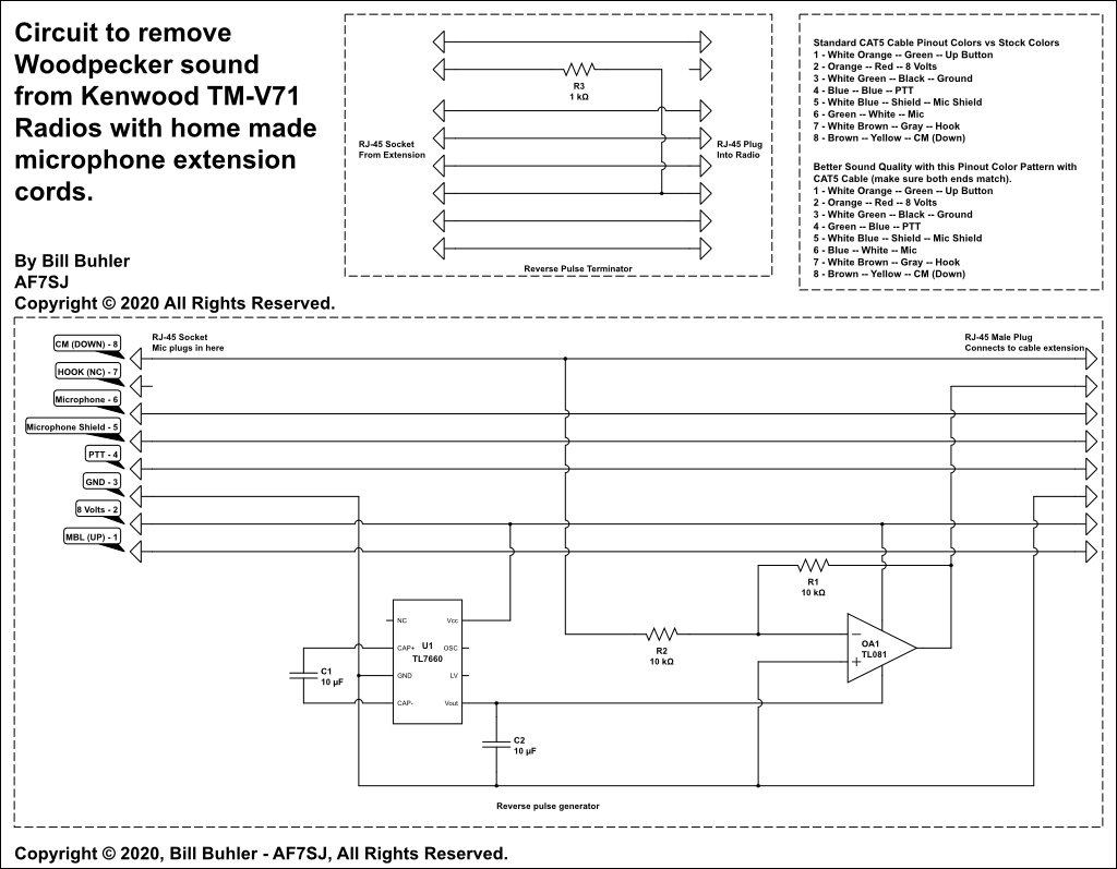
OK, so after a lot more experimenting I think I found a much simpler solution. It just so happens that the serial data causing the pulsing noise is on the orange pair, white orange wire. The orange wire is not connected at the radio or the microphone. So I built a quick inverting buffer circuit to go at the microphone end, and terminated the radio end through a resistor to the ground wire. Now I can faintly hear the pulsing if I turn up the receiving radio almost all the way, but it's pretty faint. Without a oscilloscope I don't know how much the reduction is, but it's dramatic.
So at this point I'm debating whether I should borrow a oscilloscope and measure both signals, or if I just move forward. I do know that David and Sherri have left Phoenix for their house in Alberta, and will be by in a few weeks. So that is my firm deadline to solve the issue.
Later on
Let me report on my final solution. I borrowed a Oscilloscope from Bob Carter - WR7Q - and built a negative power supply + op amp circuit which when the 5 volt pulse is sent down the orange wire sends a -5 volt pulse to the far end, which is then terminated to ground with a resistor. This put the pulsing sound down about thirty db on the oscilliscope. I gave the finished curicuit to David and he reported clean audio reports with his friends in AZ.
For those that are interested in doing the same thing, here is a schematic of my solution:
Icom 706mkIIg Microphone Repair Project
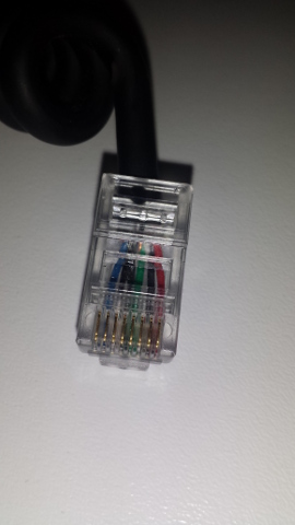
When the spring clip on my microphone broke I figured it would be a very easy repair since I've installed hundreds of rj45 crimp on connectors in my lifetime. This has ended up not being the case.
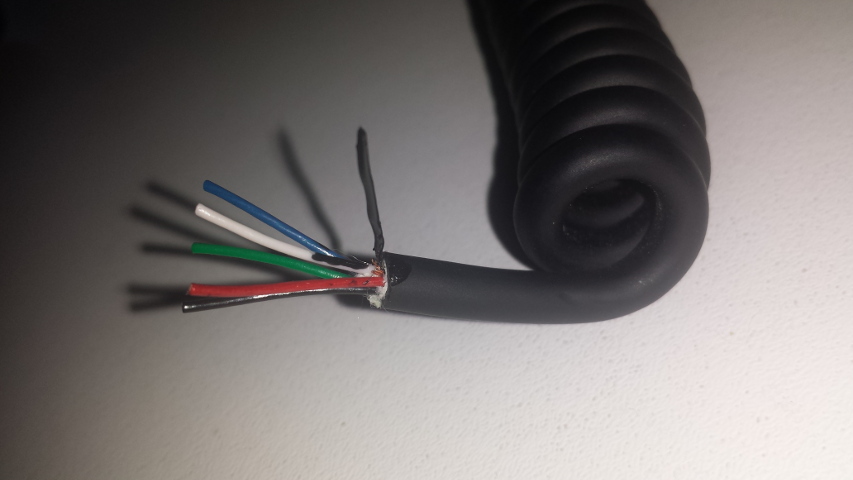
I started by chopping off the end and stripped back a little more insulation. Comparing the end I had removed with the wires revealed a problem. I had two black wires on the end but inside I was missing a wire! Instead there was shielding wrapped around the white microphone wire (which shielding I think also acts as the drain wire). Thus the microphone signal has its own shielded path along side the other microphone wires.
Feeling confused I searched online for a input and found this very useful site: Wiring Color Code and Pinouts for IC-706MkIIG and HM-103 Mic which explains that the extra black wire is the shield around the white and is somehow bonded with a regular black wire in the factory
So I obtained a short length of black 22 guage stranded wire and spliced it with the shield and soldered it all together. But this proved impossible for me to stuff into the rj45 and have end up in the right spot. Also the wires on the joint broke... So I was staring at an even shorter mic cable and needed to repeat the whole process.
I known the solder joint increased the strain of the small straneded wires too much, so I needed another way to do this. I tried heat shrink, but I couldn't find any that was a tight fit before shrinking, and what I had became too think when shrunk. But then I remembered a product I bought years ago and never got around to using until it was spoiled, Liquid Electrical Tape:
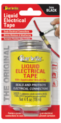
I couldn't buy some immediatly due to budget constraints, but a few weeks later I grabbed a bottle from the store and last night I began the repair for the second time.
First I twisted the braid wires together again into a single stranded conductor and coated it with a coat of black liquid electrical tape. Leaving it to dry for fifteen minutes.
After a second coat it looked pretty similar (if a little less smooth), to the other wires. With a little bit of coaxing I was able to insert the wires into the connector and verified my microphone is working. It's so nice to have my main station back in operation!
So in summary, if you need to repair a mic cord with a internally shielded wire, use liquid electrical tape to insulate the braid for a reliable and easy connection to the modular plug.
